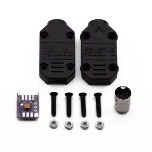
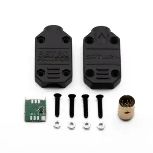
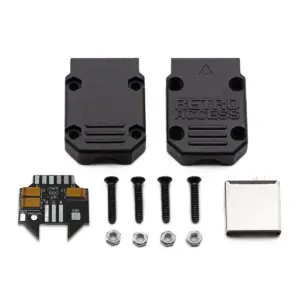
Retro Access exclusive custom-designed Housing (Hood) and Printed Circuit Board (PCB) for DIY cables. Unlike conventional designs which place components downstream at the SCART end, Retro Access boards place key signal components right at the source (console). This ensures superior signal integrity for the clearest, most accurate audio-visual experience. This kit includes all necessary circuit components pre-mounted for safe and specification compliant RGB video while aiding in clean, simplified assembly versus struggling with loose components.
DIN 8 262° is found on Sega Master System, Sega Genesis Model 1, Mega Drive Model 1. This kit is not suitable for the Japanese MK-2000 (SMS) or France (SECAM) models.
Cable selection is for the strain relief hole size only, cable is not included. The approximate diameter of Fortraflex is 7mm (0.27″), Coaxial is 9mm (0.35″).
Installation:
- Install the perfboard onto the DIN connector, verify the front orientation. Ensure the pins and solder do not protrude beyond the rear of the perfboard and solder in place.
- Mount the main PCB onto the perfboard and solder all eight tee joint pads in place.
- Close jumper JP1 “CV” for CVBS, or JP2 “CS” for CSync. Close jumper JP3 “TTL” for 5V sync only.
- Solder Red, Green, Blue conductors to R, G, B pads.
- Solder Sync, Left Audio, Right Audio conductors to S, LA, RA pads.
- Solder 5V directly to the 5V pin.
- Solder grounds to square ground pads.
- Use glue for jacket strain relief and assemble the housing.
Please contact a modding professional if you are not comfortable building DIY cables.
Features:
- Jumpers for CVBS (“CV”), Composite Sync (“CS”) and TTL.
- Series termination resistors installed directly at the console output establish 75Ω source impedance matching the cable, reducing reflections and interference for improved RGB video quality. Many other cables place these resistors inside the SCART connector, ignoring best practice and compromising video accuracy.
- Genuine Kemet premium 220 µF Tantalum AC coupling capacitors within the console connector provide clean, precise RGBS signals at the source, preventing unwanted DC bias along the cable, preserving accurate color, contrast and brightness.
- CSync attenuating 470 Ω resistor provides safe voltage for 75 Ω CSync.
All product names, logos, and trademarks, registered or unregistered, are the property of their respective owners. They are referenced on this site solely to identify compatibility. Their use does not imply any affiliation with or endorsement by those companies.